
So I am thinking myself, wouldn't be great if my home could inform me (at least by sms) that the main power supply was down and then I could reply back to the home to switch on the main circuit breaker back again so that the fridge can continue to run. Since I already have my Arduino Diecimilia lying around (and not attach to any other project) then all I need is a GSM module shield where I can program it to send sms or to receive sms to do any specific job (e.g turn on the main breaker).
After some time looking through the net (from eBay to be exact) for any cheap GSM module, my search was a disappointment. I could not get any of the module for less than USD40 plus the shipping, which is way over my budget. And also it could take me some time to learn on how to program my Arduino to communicate with those module (its been a while I'm not doing programming after quitting my job as an engineer :-P )..
Then I'm looking for other simple solution other than using the GSM module. An idea came across my mind after looking at my old-but-still-working Nokia 3310 in my storage box (i still kept the phone for a nostalgic reason). Why not just hack the phone (i'm not using that phone anyway) with some relays to duplicate the 'button-pressing' action and tell it to send sms to any number saved in the phone book. It just a simple yet cheap solution to my problem. All I need to buy is new battery and charger since the original battery was fully depleted and cannot be charge anymore. Luckily for me, there are still peoples selling the OEM battery. Fuh!
The Phone Hack
After charging the battery and switching on the phone, I'm confirmed that the phone is still working as expected. So I started to open up the covers (front and rear - just use small screwdriver to pry the left/right side). The keypad will follow the front cover easily when I open it. Then there are six small screw around the lcd panel (red-marked in picture). It is not the normal philips-type screw and I need to use the Torx T5 screw driver instead. Need to pry a little bit more on both side of the lcd screen in order to open up the panel.

Finally, I have found what I'm looking for. The PCB board! (sorry..picture taken after I soldered the wire. duh!)

Here is the close-up of the soldered wire. I just need 2 button (OK and DOWN) to control the sending sms sequence since the message and phone number are already saved in the phone itself.

Need to put some black pvc tape to prevent it from shorting and I don't want any unnecessary button press to happen. (*please note that doing this will make both buttons is unavailable to be pressed anymore. you'll need some other button on the shield to by-pass)

Done with the wires, now its time to put back the phone all together again. Start with the lcd panel, screws and finally the phone cover. Pictures below shows how I route the wires through the battery and the rear cover. This is why we need to use the thinnest wire available. Its very tight space there.


As you can see in the picture, I need to cut some small hole to taken out the wires. Or else the rear cover won't fit. Finally, I soldered 2x 2-pin connector at the end of the wires that will go to the shield board.
Now I've finished with the phone, its time to build the shield board.
The Shield Hack
Arduino is widely known for its 'shield'. Its a very versatile way to interfacing the Arduino with the outside world. Same goes to my SMS project here. I'm gonna need a shield to interface the Arduino with the phone and also to place the relays and necessary circuit to drive the relay. It is very easy to control a relay using the Arduino with help of a minimum number of component. I will not put the schematic here in my blog since I just follow what is already available from the Arduino Playground website. See here
The easiest way to build your own custom-made shield is to buy the ready-made proto-shield (or prototype shield as the full name) where you just need to solder the components on the prototype area, rather than messing with the stack-able pins and headers. Since that we cannot simply use our own protoboard (donut or perf) to make shield which is compatible to the Arduino due to its non-standard 0.16 space between the header (read here)..
Therefore I've done a few hacks on the Arduino in order to fit with my standard 0.1 donut board shield. Here are the photos:


On the shield board :

Since we already have a nice fit custom-made proto shield, now its time to place and solder other component such as relays etc.
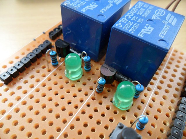
This is how the wiring look like under the board. Messy but it works for me :-)

This is the connector and wires to the phone. I put some hot glue to prevent the wires from moving and loosen. (this is the 1st version of the board. on the 2nd version, i've put a small tactile switch just beside the connector in order to by-pass the button press)


The Arduino program used in this project is simple and just using the favorite DigitalWrite( ) and Delay( ) function to turn the relay On and Off. Here is the code. You can copy, use and modify it as you pleased.
#include <Button.h>
/*
Trip Detection SMS System version 1.0 (powered by Arduino Diecimila)
Designed and Debugged by melawis501@HAFIZ, Nov 2011
Version 1.0 Rev .'A'- November 2011
*/
Button button = Button (10,PULLDOWN);
const int relayOK = 11; // set pin 11 for phone button OK
const int relayDown = 12; // set pin 12 for phone button DOWN
const int onTime = 300; //Relay On and Off timing. Adjust accordingly to suits your needs
const int offTime = 800;
void SMS_sendMsg(); // function to send the 'TRIP' message to 1st recepient
void setup() {
pinMode(relayOK, OUTPUT); // set pin 11 as OUTPUT (relay no.1)
pinMode(relayDown, OUTPUT); // set pin 12 as OUTPUT (relay no.2)
digitalWrite(relayOK,LOW); // set the state of both relays as LOW during system bootup
digitalWrite(relayDown, LOW);
}
void loop() {
if(button.isPressed()) {
SMS_sendMsg();
}
else {
digitalWrite(relayOK,LOW);
digitalWrite(relayDown,LOW);
}
}
void SMS_sendMsg(){
//Function for sending sms sequence
delay (1000);
digitalWrite(relayOK,HIGH);//relay on -- to Page 2
delay(onTime);
digitalWrite(relayOK,LOW);//relay off
delay(offTime);
digitalWrite(relayOK,HIGH); // -- to Page 3
delay(onTime);
digitalWrite(relayOK,LOW);
delay(offTime);
digitalWrite(relayOK,HIGH); // -- to Page 4 (select phone number page)
delay(onTime);
digitalWrite(relayOK,LOW);
delay(offTime);
digitalWrite(relayDown,HIGH); // -- selecting phone number
delay(onTime);
digitalWrite(relayDown,LOW);
delay(offTime);
digitalWrite(relayOK,HIGH); // -- to Page 6
delay(onTime);
digitalWrite(relayOK,LOW);
delay(offTime);
digitalWrite(relayOK,HIGH); // -- to Page 7 - Confirm sending SMS
delay(onTime);
digitalWrite(relayOK,LOW);
delay(offTime);
delay(1000);
}
Last but not least, here's the video showing me testing the SMS shield. Enjoy!
Feel free to ask me anything about the project or suggesting new ideas to share. Hope this project would benefit others, especially the Arduino communities. See again until my next project!
Arduino rocks!!